
Product Description
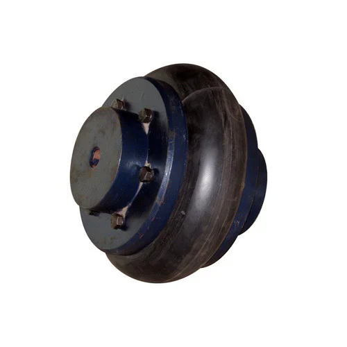
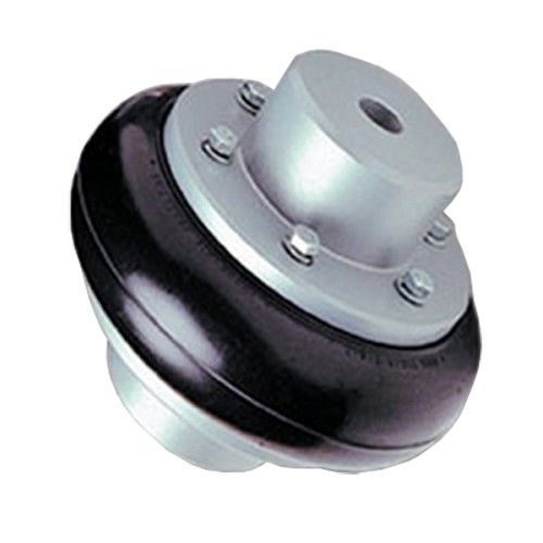
Aluminum Alloy GFC-55X49 Type Shaft Coupler Rubber Flexible Coupling
Aluminum Alloy GFC-55X49 Type Shaft Coupler Rubber Flexible Coupling
| model parameter | common bore diameter d1,d2 | ΦD | L | LF | LP | F | M | tightening screw torque (N.M) |
| GFC-14X22 | 3,4,5,6,6.35 | 14 | 22 | 14.3 | 6.6 | 5.0 | M2.5 | 1.0 |
| GFC-20×25 | 3,4,5,6,6.35,7,8,9,9.525,10 | 20 | 25 | 16.7 | 8.6 | 5.9 | M3 | 1.5 |
| GFC-20X30 | 3,4,5,6,6.35,7,8,9,9.525,10 | 20 | 30 | 19.25 | 8.6 | 5.9 | M3 | 1.5 |
| GFC-25X30 | 4,5,6,6.35,7,8,9,9.525,10,11,12 | 25 | 30 | 20.82 | 11.6 | 8.5 | M4 | 2.5 |
| GFC-25X34 | 4,5,6,6.35,7,8,9,9.525,10,11,12 | 25 | 34 | 22.82 | 11.6 | 8.5 | M4 | 2.5 |
| GFC-30×35 | 5,6,6.35,7,8,9,10,11,12,12.7,14,15,16 | 30 | 35 | 23 | 11.5 | 10 | M4 | 2.5 |
| GFC-30X40 | 5,6,6.35,7,8,9,10,11,12,12.7,14,15,16 | 30 | 40 | 25 | 11.5 | 10 | M4 | 2.5 |
| GFC-40X50 | 6,8,9,10,11,12,12.7,14,15,16,17,18,19,20,22,24 | 40 | 50 | 32.1 | 14.5 | 14 | M5 | 7 |
| GFC-40X55 | 6,8,9,10,11,12,12.7,14,15,16,17,18,19,20,22,24 | 40 | 55 | 34.5 | 14.5 | 14 | M5 | 7 |
| GFC-40X66 | 6,8,910,11,12,12.7,14,15,16,17,18,19,20,22,24 | 40 | 66 | 40 | 14.5 | 14 | M5 | 7 |
| GFC-55X49 | 10,11,12,12.7,14,15,16,17,18,19,20,22,24,25,28,30,32 | 55 | 49 | 32 | 16.1 | 13.5 | M6 | 12 |
| GFC-55X78 | 8,10,12,12.7,14,15,16,17,18,19,20,22,24,25,28,30,32 | 55 | 78 | 46.4 | 16.1 | 19 | M6 | 12 |
| GFC-65X80 | 14,15,16,17,18,19,20,22,24,25,28,30,32,35,38,40 | 65 | 80 | 48.5 | 17.3 | 14 | M8 | 20 |
| GFC-65X90 | 14,15,16,17,18,19,20,22,24,25,28,30,32,35,38,40 | 65 | 90 | 53.5 | 17.3 | 22.5 | M8 | 20 |
| GFC-80X114 | 19,20,22,24,25,28,30,32,35,38,40,42,45 | 80 | 114 | 68 | 22.5 | 16 | M8 | 20 |
| GFC-95X126 | 19,20,22,24,25,28,30,32,35,38,40,42,45,50,55 | 95 | 126 | 74.5 | 24 | 18 | M10 | 30 |
| model parameter | Rated torque (N.M)* |
allowable eccentricity (mm)* |
allowable deflection angle (°)* |
allowable axial deviation (mm)* |
maximum speed rpm |
static torsional stiffness (N.M/rad) |
moment of inertia (Kg.M2) |
Material of shaft sleeve | Material of shrapnel | surface treatment | weight (g) |
| GFC-14X22 | 5.0 | 0.1 | 1 | ±02 | 10000 | 50 | 1.0×10⁻⁶ | High strength aluminum alloy | Polyurethane imported from Germany | Anodizing treatment | 10 |
| GFC-20X25 | 5.0 | 0.1 | 1 | ±02 | 10000 | 50 | 1.0×10⁻⁶ | 15 | |||
| GFC-20X30 | 5.0 | 0.1 | 1 | ^02 | 10000 | 53 | 1.1×10⁻⁶ | 19 | |||
| GFC-25X30 | 10 | 0.1 | 1 | 10000 | 90 | 5.2X10⁻⁶ | 33 | ||||
| GFC-25X34 | 10 | 0.1 | 1 | £)2 | 10000 | 90 | 5.2×10⁻⁶ | 42 | |||
| GFC-30X35 | 12.5 | 0.1 | 1 | ±02 | 10000 | 123 | 6.2×10⁻⁶ | 50 | |||
| GFC-30×40 | 12.5 | 0.1 | 1 | 102 | 10000 | 123 | 6.2×10⁻⁶ | 60 | |||
| GFC-40X50 | 17 | 0.1 | 1 | 8000 | 1100 | 3.8×10⁻⁵ | 115 | ||||
| GFC-40X55 | 17 | 0.1 | 1 | ±02 | 8000 | 1100 | 3.8×10⁻⁵ | 127 | |||
| GFC-40X66 | 17 | 0.1 | 1 | 7000 | 1140 | 3.9×10⁻⁵ | 154 | ||||
| GFC-55X49 | 45 | 0.1 | 1 | ±02 | 6500 | 2350 | 1.6×10⁻³ | 241 | |||
| GFC-55X78 | 45 | 0.1 | 1 | 102 | 6000 | 2500 | 1.6×10⁻³ | 341 | |||
| GFC-65X80 | 108 | 0.1 | 1 | ±02 | 5500 | 4500 | 3.8×10⁻³ | 433 | |||
| GFC-65X90 | 108 | 0.1 | 1 | ±02 | 5500 | 4800 | 3.8×10⁻³ | 583 | |||
| GFC-80X114 | 145 | 0.1 | 1 | £)2 | 4500 | 5000 | 1.8×10⁻³ | 1650 |
/* January 22, 2571 19:08:37 */!function(){function s(e,r){var a,o={};try{e&&e.split(“,”).forEach(function(e,t){e&&(a=e.match(/(.*?):(.*)$/))&&1
Maintaining and Preserving Rubber Coupling Performance
To ensure the longevity and optimal performance of rubber couplings, the following best practices should be observed:
- Regular Inspections: Perform visual inspections for signs of wear, cracks, or damage.
- Lubrication: Apply appropriate lubricants to minimize friction and extend rubber life.
- Alignment: Maintain proper alignment between connected shafts to prevent undue stress on the coupling.
- Temperature Control: Monitor operating temperatures to prevent overheating that can accelerate rubber degradation.
- Load Monitoring: Avoid overloading the coupling beyond its rated capacity.
- Vibration Analysis: Monitor vibration levels and address excessive vibrations promptly.
- Regular Maintenance: Follow manufacturer’s recommendations for maintenance schedules.
- Replacement: Replace worn or damaged rubber elements as needed.
By adhering to these practices, the performance and service life of rubber couplings can be effectively preserved.
Common Rubber Materials Used in Manufacturing Rubber Couplings
Various rubber materials are used in the manufacturing of rubber couplings, each chosen based on its specific properties and the intended application:
- Neoprene: Known for its oil and chemical resistance, neoprene rubber is used in couplings that require durability and resistance to harsh environments.
- Nitrile: Nitrile rubber offers excellent oil and fuel resistance, making it suitable for applications in machinery that involve contact with lubricants.
- Natural Rubber: Natural rubber provides good elasticity and flexibility, making it suitable for couplings requiring high levels of shock and vibration absorption.
- EPDM: Ethylene Propylene Diene Monomer (EPDM) rubber offers good resistance to weather, ozone, and aging, making it suitable for outdoor or high-temperature applications.
- Polyurethane: Polyurethane rubber offers high abrasion resistance and can handle higher load capacities, making it suitable for heavy-duty applications.
The choice of rubber material depends on factors such as the operating environment, chemical exposure, temperature range, flexibility requirements, and load conditions. Engineers select the appropriate rubber material to ensure the coupling’s performance and longevity in specific applications.
Main Advantages of Using Rubber Couplings in Industrial Applications
Rubber couplings offer several key advantages when used in industrial applications. These advantages make them a popular choice for various industries and mechanical systems:
- Misalignment Tolerance: Rubber couplings can accommodate angular, parallel, and axial misalignments between connected shafts, reducing the need for precise alignment during installation and operation.
- Vibration Damping: The rubber elements of these couplings absorb and dampen vibrations, minimizing the transmission of vibrations and shocks to other components. This helps prevent damage, wear, and noise generation.
- Shock Absorption: In systems where sudden shocks or impacts occur, rubber couplings absorb and cushion the impact, protecting connected components from damage.
- Noise Reduction: The ability to dampen vibrations also contributes to noise reduction, creating quieter operation environments for machinery and equipment.
- Equipment Protection: Rubber couplings protect sensitive equipment from excessive loads, vibrations, and shocks, enhancing the longevity and reliability of the system.
- Cost-Effectiveness: Compared to some other coupling types, rubber couplings are generally cost-effective to manufacture, purchase, and maintain.
- Easy Installation: The flexibility and design of rubber couplings make them relatively easy to install without the need for specialized tools or complex procedures.
- Minimal Maintenance: Rubber couplings require minimal maintenance and lubrication, reducing downtime and maintenance costs.
- Wide Range of Applications: Rubber couplings are versatile and find applications in various industries, including automotive, power generation, pumps, conveyors, and more.
In summary, the main advantages of using rubber couplings in industrial applications include their ability to tolerate misalignment, dampen vibrations, absorb shocks, reduce noise, protect equipment, cost-effectiveness, easy installation, low maintenance requirements, and suitability for a wide range of applications.


editor by CX 2024-04-04